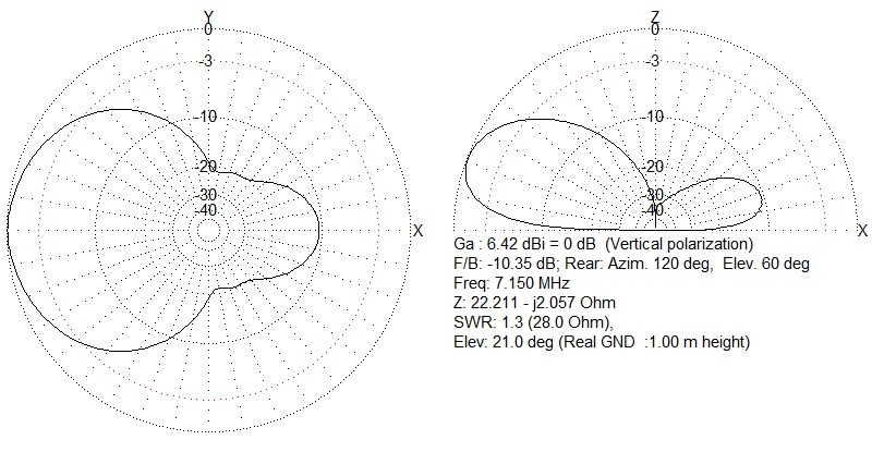
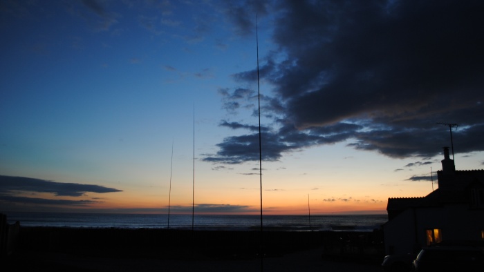
Essentially, this is a single 1/4 wave vertical antenna with ground radials, complimented by a pair of parasitic verticals; a reflector and a director. It will deliver around 6db of additional gain over a standard vertical with a beamwidth of around 70 degrees. I have built mine pointing 300 degrees so that I can work the US easily at night.
I call this the M0MCX VPA (Vertical Parasitic Array).
Hours of planning and modelling with MMANA has finally produced an excellent and extremely economical method of producing gain in one direction, although the front-to-back ratio isn’t superb, it still has some rejection.

The construction method is very easy and each element is based on a spacing of 11m between each vertical element. The following dimensions produce a perfect match at 7.1Mhz.

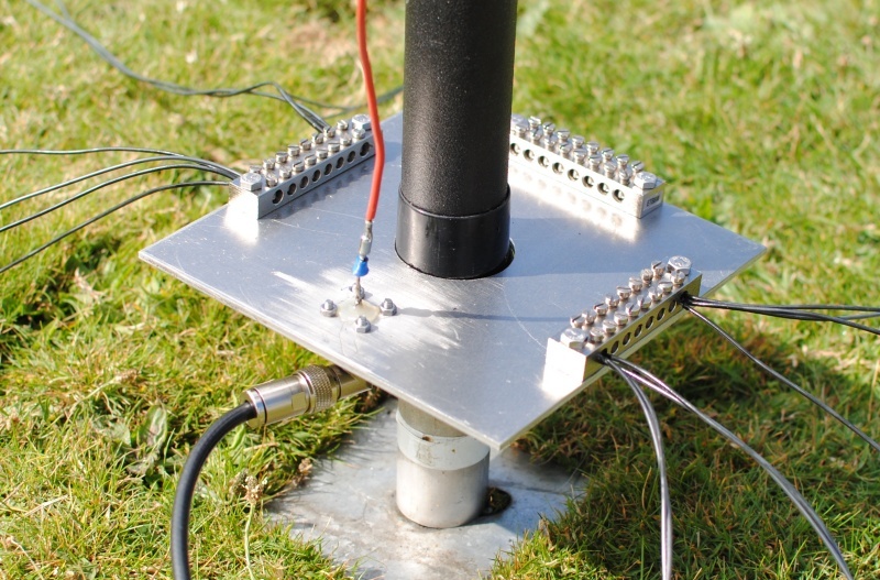
- The driven element has 16 ground radials and is cut (tuned) for 7.255 Mhz (measured at 936 cms)
- The front (director) element has 4 ground radials is tuned for 7.395 Mhz (measured at 916 cms)
- The rear (reflector) element has 4 ground radials is tuned for 7.035 Mhz (measured at 976 cms)
Tip: Once the main driven element is built, you will find that the director element needs to be around 20cms shorter and the reflector is approximately 40cms longer.

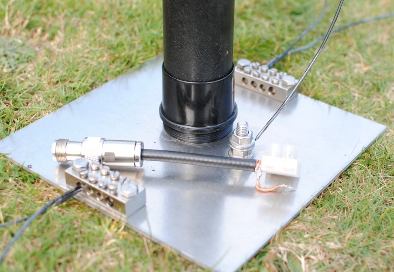
Pigtail to allow temporary connection to parasitic element to check tuning.
Matching: Depending on the ground conditions, the match you will achieve might not be perfect. The original modelling that I conducted suggested that I would achieve around 25 ohms. I had built a 1:2 balun ready for implementation at the feedpoint, however in practice, the impedance is actually 49 ohms at resonance – which with the above lengths gives me a perfect match at 7.10 Mhz (the MJF analyser actually says SWR of 1.0 which I have never had before!). I am achieving better than 1:1.2 SWR across the whole band. For those world-wide amateurs with access to the 7.2 – 7.3Mhz, you will still achieve better than 1:1.4 SWR even at 7.3Mhz. At 7.0mhz, I am showing an SWR of 1:1.2.
Coax feed: Because impedance repeats every half wavelength, I had pre-cut a full wavelength of coax, less the amount of the Velocity Factor (VF). This way, I can make measurements in the shack, accurately without having to venture outside. I used a 50 ohm coax with a VF of 0.82. The length of my coax is therefore around 34.5 metres. Of course, you could also use a wavelength (or multiple of any half-wave length) of 75 ohm coax too, as long as it’s cut accurately according to the VF since the impedance at the feedpoint will be the same at the termination (rig) end.
Originally, I was going to build this as a switchable array, firing West or East with relays and a couple of coils however I ran out of time in the end before my holiday so this is just a test bed.
Conclusion: In operation, the VPA delivers around 2 to 3 S points over a single vertical or a dipole for DX (more than 3,000 miles) and is extremely worthwhile for marginal signals. This antenna has allowed me to run huge pile-ups to the USA with the beam-width just about wide enough to run South America too. For some reason, long-path ZL is also quite achievable. Probably off the back of the array. Check out the sound-clip below recorded on the morning of 25th August 2014.
Listen to the quality of long-path reception from ZL.
Next up is to make this switchable with relays to swap the elements over at the flick of a switch. This will allow East or West firing, Dual firing (East / West by shortening both elements) as well as forcing North-South firing (by lengthening both elements). I’ll report back when complete.
Check out the gallery:
Callum M0MCX.


